Control PWM fan using PID and temp sensors with Arduino
Objectives
In this post I explain how to realize a self regulating fan cooling system using Arduino.
In my case I wanted to cool a custom NAS placed in a closet, using two fans (in and out).
I also wanted to act on the difference between internal and external temperature. Indeed, it’s a nonsense to set a 25° temperature when outside it’s 30°.
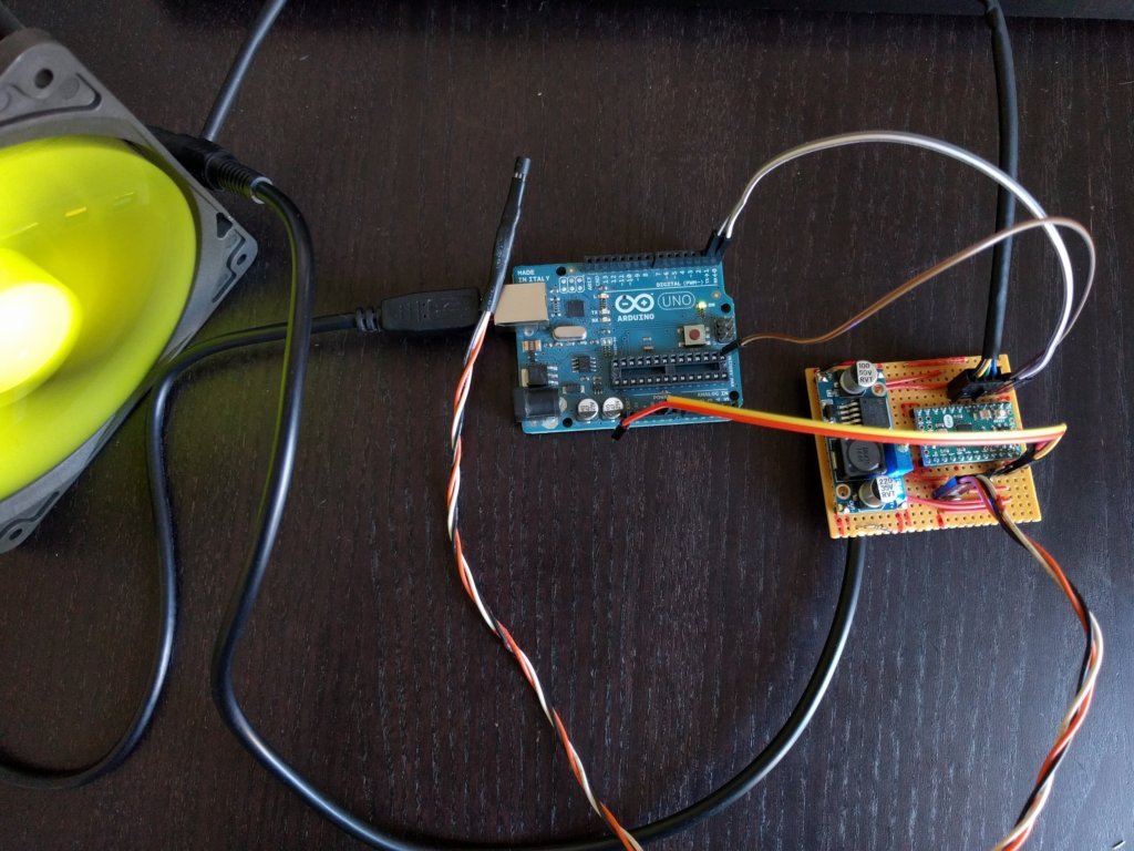
Figure 1. Whole setup
PID Control
PID (Proportional Integral Derivative) is a common way to regulate a system, widely used in industry.
A PID controller continuously delivers a command signal to reach a fixed setpoint. Measurements allows to calculate an error to adjust the command signal.
Learn more about PID (wikipedia).
In this project I’m using this great PID library.
It’s really simple to setup, but, as said everywhere : the real tricky part is to set kp, ki and kd, according your needs and configuration.
PWM Fan
PWM (Pulse Width Modulation) fans are very common, and could be found in computers, networks components…
This fans are modulated using PWM and could be monitored through a tachymeter output.
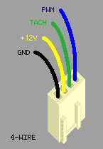
Figure 2. Standard PWM fan pinout
In my case, I’ve bought Coolink SWiF2-120P, capable of a 36CFM@12v, that could be found here on amazon
Electronic setup
Arduino
I’ve chose Arduino Mini for this project, but it could be exhanged by most of standard Arduino boards.
Arduino Mini is very compact, but has no USB interface. You’ll need an external programming board, such as another (regular) Arduino board.
There’s a lot of resources to learn doing this, an example here.
Power
Fans are powered with +12v source. I’ve planned to power Arduino Mini using the same power adapter, with a voltage regulator.
I’ve chose a LM2596 DC to DC, which could be found on amazon here.
Temperature sensors
I’m using two standard LM35 temperature sensor. There’s a lot of resource about using it easily with Arduino, as in this Arduino Playground article.
One sensor is directly sold on the board for internal measure, the other is attached to a cable for external measurement.
Wiring
For this small project, I’ve created a simple stripboard.
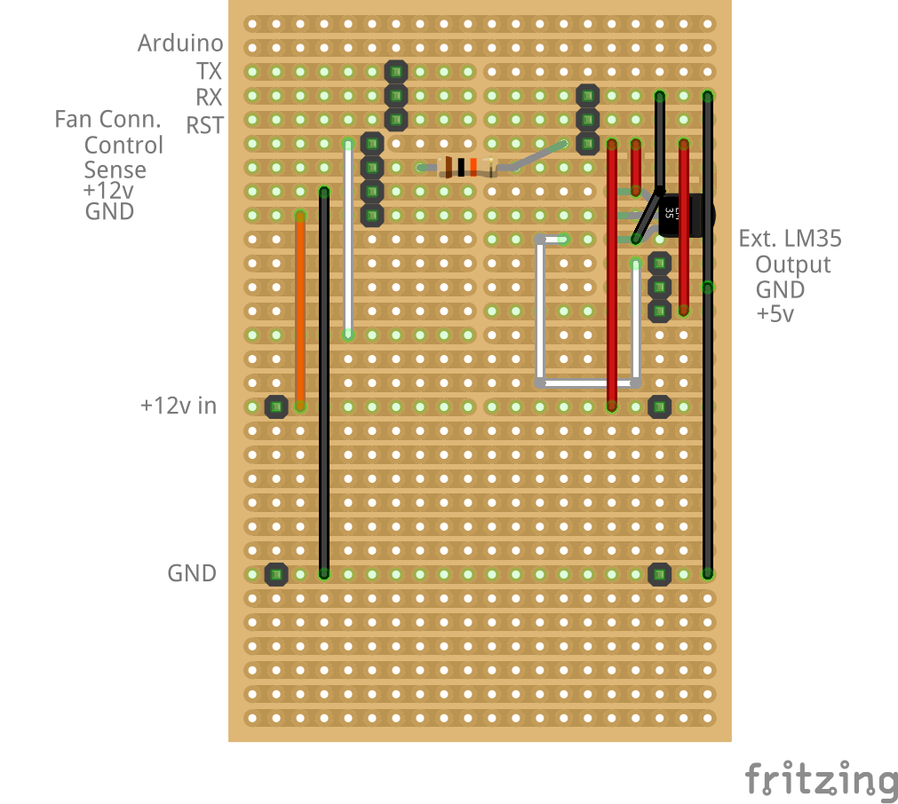
Figure 3. Fritzing schematics without Arduino Mini
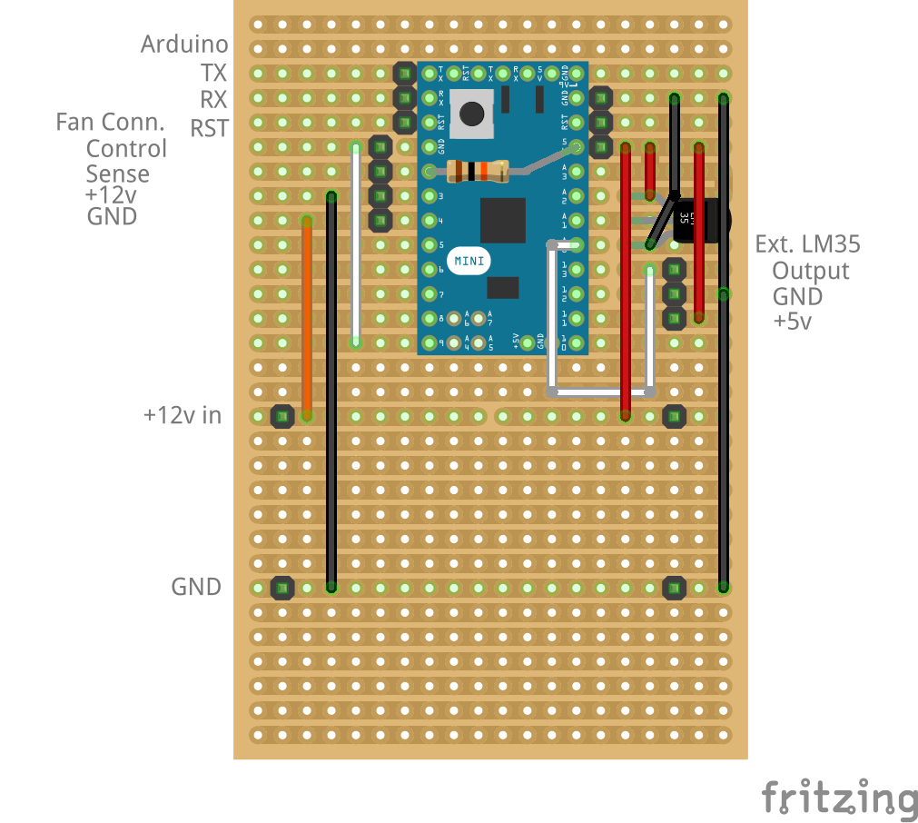
Figure 4. Fritzing schematics with Arduino Mini
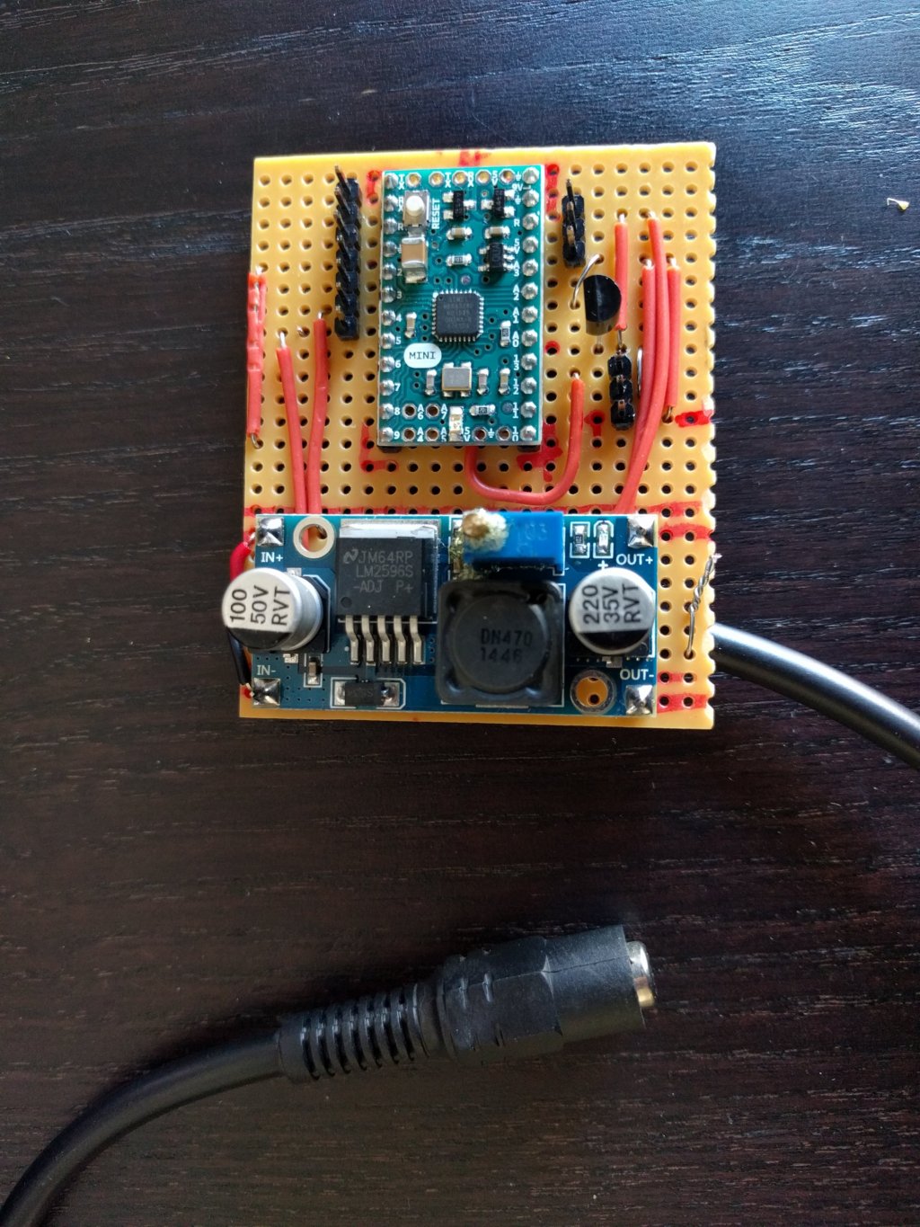
Figure 5. The board alone
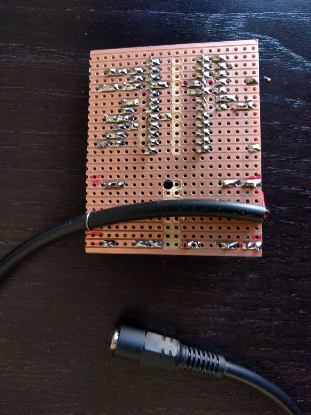
Figure 6. Backside of the board

Figure 7. Connected to a regular Arduino
Software
Arduino code
pwm_pid.ino
#include <PID_v1.h>

int fanPulse = 2;   //tachymeter fan pin
int fanControl = 9; //pwn fan pin
int pinTempInt = 1; //internal temp sensor pin
int pinTempExt = 0; //external temp sensor pin
int avgLoop = 5;    //temp measurement loops

//PID parameters. I'm using defaults with quite nice results
double kp=2;   //proportional parameter
double ki=5;   //integral parameter
double kd=1;   //derivative parameter

//Setpoint (Maximum difference between internal and external temperature)
double maxTdiff = 5;

//Minimum and Maximum PWM command, according fan specs and noise level required
double commandMin = 0;
double commandMax = 250;

double tempInt, tempExt, tempDiff, command;
unsigned long pulseDuration;

//init PID
PID myPID(&tempDiff, &command, &maxTdiff,kp,ki,kd, REVERSE);

boolean first = true;

void setup()
{
  Serial.begin(9600);

  pinMode(fanPulse, INPUT);
  digitalWrite(fanPulse,HIGH);
  pinMode(fanControl, OUTPUT);

  tempInt = getTempInt();
  tempExt = getTempExt();

  tempDiff = tempInt - tempExt;
  if(tempDiff < 0) {
    tempDiff = 0;
  }

  //turn the PID on
  myPID.SetMode(AUTOMATIC);
  myPID.SetOutputLimits(commandMin, commandMax);
}

//internal temp
double getTempInt() {
  return getTemp(pinTempInt);
}

//external temp
double getTempExt() {
  return getTemp(pinTempExt);
}

//get temp of pin sensor
double getTemp(int pin) {
  double rawTemp;
  rawTemp = analogRead(pin);
  double temp = rawTemp * (5.0 / 1023.0 * 100.0);
  return temp;
}

//get current fan speed
double getFanSpeed() {
  pulseDuration = pulseIn(fanPulse, LOW);
  double frequency = 1000000/pulseDuration;
  return frequency / 4 *60;
}

//print log firstline
void header() {
  Serial.println("PID Setup");
  Serial.print("kp [");
  Serial.print(kp);
  Serial.println("]");
  Serial.print("ki [");
  Serial.print(ki);
  Serial.println("]");
  Serial.print("kd [");
  Serial.print(kd);
  Serial.println("]");
  Serial.print("maxTdiff [");
  Serial.print(maxTdiff);
  Serial.println("]");

  first=false;
}

//display log line
void mainDisplay() {
  Serial.print("Avg T.int [");
  Serial.print(tempInt);
  Serial.print("], Avg T.ext [");
  Serial.print(tempExt);
  Serial.print("], Avg Tdiff [");
  Serial.print(tempDiff);
  Serial.print("], Command [");
  Serial.print(command);
  Serial.print("], RPM [");
  Serial.print(getFanSpeed());
  Serial.println("]");
}

//display temp measurements before avg processing
void curTempDisplay(double tInt, double tExt) {
  Serial.print("T.int [");
  Serial.print(tInt);
  Serial.print("], T.ext [");
  Serial.print(tExt);
  Serial.println("]");
}

void loop()
{
  if(first) {
    header();
  }

  //this loop is a trick to get a more stable temp, under +5v LM35 is quite unprecise...
  double avgInt = 0;
  double avgExt = 0;
  for(int i=0; i < avgLoop; i++) {
    double tInt = getTempInt();
    double tExt = getTempExt();
    avgInt += tInt;
    avgExt += tExt;
    curTempDisplay(tInt, tExt);
    delay(1000);
  }

  //calculate setpoint (tempDiff)
  tempInt = avgInt / avgLoop;
  tempExt = avgExt / avgLoop;
  tempDiff = tempInt - tempExt;
  if(tempDiff < 0) {
    tempDiff = 0;
  }

  //process PID
  myPID.Compute();

  //apply PID processed command
  analogWrite(fanControl, command);

  //display log
  mainDisplay();
}
Monitoring
It’s possible to visualize debug output using Arduino software Serial Monitor, screen or tail.
Screen monitoring using screen
screen /dev/ttyACM0 9600Screen monitoring using tail
tail -f /dev/ttyACM0Links
Hardware.fr tests of 63 120mm fans (fr)
Hardware.fr tests of Coolink SWIF2 (fr)