aAlarm : Intrusion detection with an Arduino based Alarm
New version
Before reading
This describes an old version.
Update version links :
Introducing aAlarm
aAlarm is an intrusion detector, with a dynamic web monitor.
aAlarm projet is based Arduino, a PC, a few custom electronic boards, and appropriate software.
aAlarm stands for Arduino Alarm.
My long term objective is to build a complete home automation modular system based on Arduino, so this project should be considered as a first step to a bigger one.
It’s currently based on a touch sensor (a temporary switch), which could be used to protect a door, or a window, anything that opens and closed.
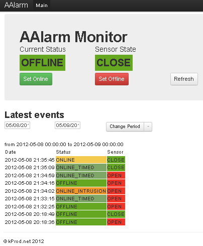
Figure 1. Web Monitor running in a browser window
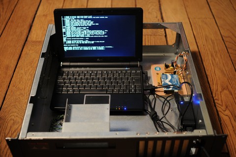
Figure 2. Project case including PC and electronics
Update !
This project is still a beta version. After a few weeks of using AAlarm, I’ve noticed some problems.
-
Arduino Timer lib seems to be unstable ; after a few days, timers would not reset…
-
Serial/USB connection is also unstable. So far, I have not found a better solution than to reset Perl script
Future updates
Arduino unstability may force me to move more functions to Perl Script.
aAlarm would be less computer independant, more like an I/O entity drove by Perl Script.
Functional details
The big picture
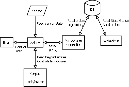
Figure 3. Functional view of aAlarm
The core of aAlarm is a PC running a Perl program.
The Perl program drives the Arduino via serial/usb. It also interact with the web monitor, allowing users to read aAlarm state and send commands.
Arduino is used as an interface enabling communication between electronics and the core system (PC / Perl)
How it works
When in appropriate state (ONLINE), it will be able to detect an intrusion. It must be deactivated before switching to an alarm state (trigger a siren, and sending an alert email). See part 2 to know the details.
In this project, Arduino is used as the I/O part of the project. It reads inputs, such as the open/close sensor. It also drives the keypad (through I2C), and a piezo siren.
aAlarm state could be changed from a keypad (using a secret code) or by using a web admin page control.
A PC is connected to the USB port on the Arduino board. Its purpose is to interact with Arduino board, through a web page. It also provides independent power to the whole system ; in case of electrical failure, aAlarm is powered through the eeepc battery.
To provide the web control page, Apache server serves a couple of PHP files. A Perl script is used to interact with Arduino through USB/Serial port. We also use a MySQL database to store aAlarm history and read/control AAlarm state. Statuses
aAlarm use 7 different statuses:
-
OFFLINE : Alarm is offline
-
ONLINE_TIMED : Waiting user to exit the controlled area.
-
ONLINE : Alarm is online
-
INTRUSION : An intrusion has been detected.
-
INTRUSION_WARNING : Intruder is warned to compose code on keypad.
-
INTRUSION_ALARM : Code have not been composed correctly. Siren is rang, mail is sent. Alert !
-
UNKNOWN : Cannot determine status. Would be a communication problem.
aAlarm sensors use 3 states:
-
OPEN
-
CLOSE
-
UNKNOWN : Cannot determine state. Would be a communication problem.
Status control
Status could be changed using either the keypad or the web admin.
With the keypad, status changes could be :
-
OFFLINE to ONLINE, with a customisable delay (ONLINE_TIMED will be used between)
-
ANY STATE but OFFLINE to OFFLINE (disabling)
When ONLINE status is active, if sensor state changes (CLOSE to OPEN) once, INTRUSION status is triggered.
When INTRUSION status is active :
-
A first timer is started to trigger INTRUSION_WARNING status
-
Another timer will trigger INTRUSION_ALARM status
Any time, since ONLINE to INTRUSION_ALARM statuses, aAlarm could be deactivated, using keypad or web admin.
All status and sensor states are recorded to the database.
Modules
The aAlarm electronic part is divided into 3 components
-
A main board, which is directly connected to Arduino
-
A power conversion board
-
A keypad board, which is connected to main through I2C
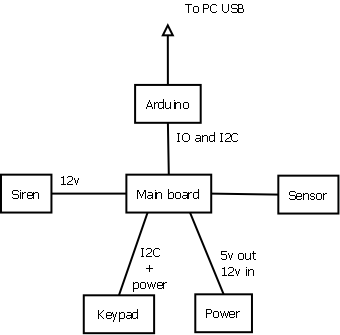
Figure 4. Hardware modules functional view
Main Board
Our mainboard is quite simple ; it’s mainly a connection board. Arduino is connected by 2 lines of pins. Connectors provided :
-
Sensor connector
-
Power exchange (to get 12v in exchange of 5v)
-
Keypad (I2C line)
-
Siren (powerded by 12v)
-
Siren keylock (option)
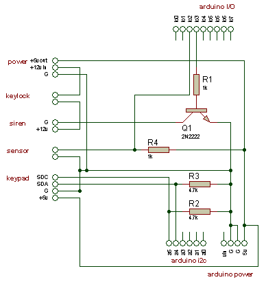
Figure 5. Main board schematics
Power board
Converts 5v (from USB/Arduino) to 12v to provided current to the siren (200mA max). The circuit is based on a LM2577 current converter. I’ve used a typical circuit available on Internet.
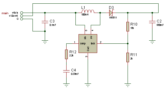
Figure 6. Power Board
Keypad board
Connected through I2C Arduino line, it provides an physical interface to enter digits by a 3x4 matrix keypad. This board also drives 2 leds, indicating ONLINE / OFFLINE status, and a piezo buzzer, to warn user before 12v siren.
Using I2C allows to connect keypad to main board using a 4 wire cable. Keep in mind that I2C operates within 2 meters.
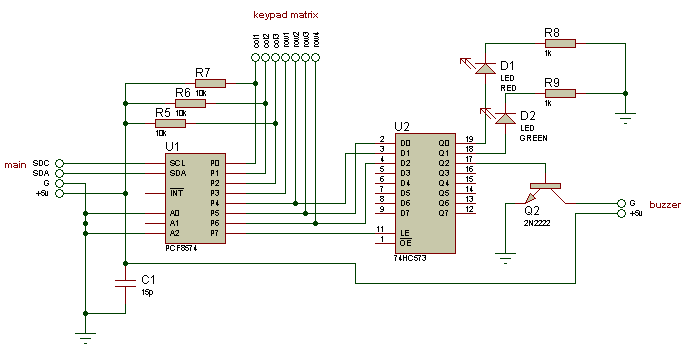
Figure 7. Keypad board
Arduino Software
Objectives
Our Arduino board must be able to :
-
Read sensor state
-
Receive pressed keys from keypad and drive keypad leds and buzzer through I2C
-
Drive siren
-
Interact with an external program (Perl for instance) through serial over USB
-
Keep track of current status
Libraries
To achieve this, we’ll use some useful libraries :
-
i2cKeypad
-
Password
-
SimpleTimer
i2cKeypad
Used to drive my i2c keypad through Arduino i2c port. I’ve modified it to make it compatible with led and buzzer on same i2c port.
I used this tutorial on keypad v0.3 of Mark Stanley
Sources
WebMonitor
Control aAlarm from anywhere
AAlarm is monitored using a web page (Web Monitor).
Web Monitor allows to view current status or past events, and to control remotely AAlarm.
AAlarm is also able to send mail when a specific status is reach.
Database
I’m using a really simple MySQL database.
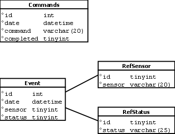
Figure 8. Database tables
Perl Script
AAController.pl is an interface between AAlarm and external world (Web Monitor). It communicates with Arduino board using Serial over USB.
AAController is continuously requesting AAlarm to update DB if status or state is changed. For each change, an Event entry is created.
AAController also reads Commands in DB and scan for a new entry. If a new entry is found, the command is sent to AAlarm.
Note that mail sending feature is not active in this version (see mailSend function, commented in AAController.pl)
Web part
Web Monitor consists in a PHP page allowing user to check current Status and State, viewing events history, and send commands to AAlarm.
Status and state are read from DB. Commands are recorded to DB.
Web Monitor features JQuery (Ajax..) and Bootstrap CSS.
Figure 9. Web Monitor running in a browser window
Media
Project pictures
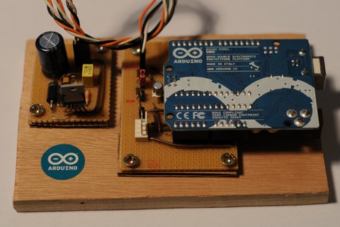
Figure 10. Main and power boards, fixed on a wooden plate
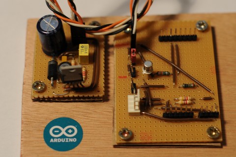
Figure 11. Main and power boards, with Arduino board removed

Figure 12. Keypad with its awful home made enclosure. Used to be a chocolate box :)
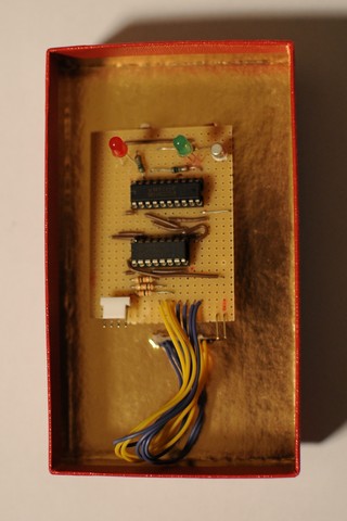
Figure 13. Keypad board
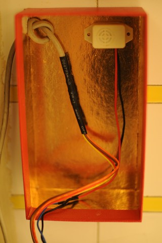
Figure 14. Wall mount, with buzzer

Figure 15. Main Box, based on a second hand Cisco 3U box :)
Figure 16. Eeepc 1000h with lid open, boards and laptop power
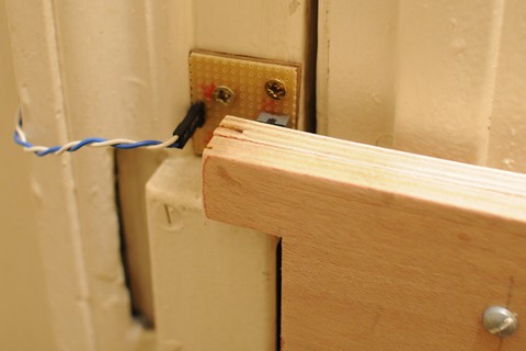
Figure 17. Door sensor, closed
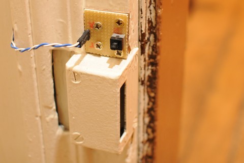
Figure 18. Door sensor, open
Video
First software version (sending mails, no web interface). Comments in french :)
Youtube aAlarm presentation